

Enthalpy of moist air is the total heat content of an air-water vapor mixture, expressed per unit mass of dry air in kJ per kilogram of dry air, combining the sensible heat carried by dry air and the latent heat bound in water vapor. This article defines the enthalpy calculation formula, breaks down each component, walks through a plain-language worked example at standard conditions, and explains how HVAC engineers apply enthalpy values to coil sizing, air handling unit selection, and energy recovery ventilator specification.
Understanding enthalpy is not optional in heating, ventilation, and air conditioning (HVAC) system design. Every coil sizing decision, every air handling unit (AHU) specification, and every energy recovery calculation reduces to an enthalpy difference between two air states.
Key Takeaways
- Specific enthalpy of moist air equals dry-air sensible enthalpy (approximately 1.006 kJ/kg·°C multiplied by dry-bulb temperature) plus humidity ratio multiplied by water vapor enthalpy (approximately 2501 + 1.86t kJ/kg), expressed in kJ per kilogram of dry air.
- The standard reference datum sets dry air enthalpy to 0 kJ/kg at 0°C and water vapor latent heat of vaporization to 2501 kJ/kg at 0°C. Enthalpy values from different software tools are not directly comparable unless their reference datums match.
- At elevation, reduced barometric pressure increases the humidity ratio achievable at a given dry-bulb temperature and relative humidity, which raises the latent component of specific enthalpy and requires correction for accurate AHU sizing.
- Energy recovery ventilator (ERV) performance must be evaluated on enthalpy effectiveness, not sensible effectiveness alone, per ASHRAE Standard 84-2020. A unit selected on sensible efficiency only will systematically underperform its latent recovery targets.
- The enthalpy difference between entering and leaving air states, multiplied by mass flow rate, determines the total heat load on any HVAC coil, making enthalpy the primary sizing input for heating and cooling equipment.
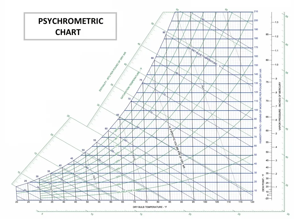
- Adiabatic humidification adds latent enthalpy at nearly constant sensible enthalpy, which is why it appears as a near-horizontal line on the psychrometric chart, distinct from steam humidification, which increases both components.
What Enthalpy Means in the Context of Moist Air
In thermodynamics, enthalpy represents the total heat content of a system at constant pressure. For HVAC engineers, the relevant system is moist air: a mixture of dry air and water vapor that together carry two distinct forms of thermal energy.
Dry air carries sensible heat, which changes with dry-bulb temperature and registers directly on a thermometer. Water vapor carries latent heat, the energy stored in the phase change from liquid water to vapor, which does not register as a temperature change. Because atmospheric water vapor can represent up to roughly 3 percent of air mass by weight, and because latent heat values are large relative to sensible heat values, both components must be accounted for in any accurate HVAC load calculation.
Specific enthalpy is expressed per unit mass of dry air, not per unit mass of the moist air mixture. This convention simplifies calculations because the mass of dry air remains constant even as humidity ratio changes.
Understanding what relative humidity is alongside enthalpy is useful because relative humidity (RH) determines how much water vapor the air actually holds relative to its maximum capacity at that temperature.
Sensible Heat and Latent Heat: The Two Components of Moist Air Enthalpy
Sensible heat is the energy that changes dry-bulb temperature. It is measurable, predictable, and proportional to temperature change at a known specific heat capacity. Latent heat is the energy stored in water vapor that does not register as a temperature change. It is released or absorbed during phase changes, such as when water evaporates into the air stream.
Both components must be included in any honest HVAC energy accounting. Ignoring latent heat produces systematically undersized equipment, particularly in humid climates and high-occupancy spaces where moisture loads are significant.
The Specific Enthalpy Formula for Moist Air
The standard enthalpy calculation formula for moist air is:
h = hₐ + x · hw
Where h is specific enthalpy of moist air in kJ/kg dry air, hₐ is specific enthalpy of dry air, x is humidity ratio in kg water per kg dry air, and hw is specific enthalpy of water vapor. Each term carries physical meaning beyond its algebraic role.
The humidity ratio, also called specific humidity, is the mass of water vapor carried per unit mass of dry air. Even small changes in humidity ratio produce large changes in total enthalpy because water vapor enthalpy values are large. This is why psychrometrics treats humidity ratio as a primary state variable alongside dry-bulb temperature.
Imperial unit variants of this formula exist but are not addressed in detail here. Engineers working in British thermal units should verify their formula coefficients against ASHRAE Fundamentals Handbook Chapter 1, as the conversion is not a simple scaling factor.
Dry Air Specific Enthalpy: The Sensible Heat Component
The dry air component is:
hₐ = 1.006 · t
Where t is dry-bulb temperature in degrees Celsius and 1.006 kJ/kg·°C is the specific heat of dry air. This linear relationship holds well across the temperature range relevant to HVAC practice, approximately -40°C to 65°C.
The reference datum sets hₐ to 0 kJ/kg at 0°C by convention. This is not an absolute thermodynamic statement that air contains no energy at 0°C. It is a calculation baseline. Sub-zero dry-bulb temperatures therefore produce negative dry-air enthalpy values, which is mathematically correct and physically meaningful within the convention.
Water Vapor Specific Enthalpy: The Latent Heat Component
The water vapor component is:
hw = 2501 + 1.86t
The 2501 kJ/kg figure is the latent heat of vaporization of water at 0°C. The 1.86 kJ/kg·°C term accounts for the sensible heat of water vapor above 0°C. At moderate HVAC temperatures, the 2501 kJ/kg term dominates.
This dominance is significant. Even when humidity ratio is small, multiplying a small x by a very large hw produces a latent enthalpy contribution that rivals or exceeds the sensible component. This mechanism explains why humidification adds meaningful energy to an air stream at nearly constant dry-bulb temperature, and why absolute humidity and relative humidity both matter to load calculations, not just one or the other.
Worked Example: Calculating Enthalpy at a Specific Air State
Consider a realistic indoor design condition: dry-bulb temperature of 25°C and relative humidity of 50%. This is a common starting point for comfort and process conditioning analysis, and it illustrates how the enthalpy calculation formula works in practice.
- Determine saturation pressure of water vapor at 25°C: approximately 3.17 kPa. Calculate partial pressure of water vapor: 0.50 × 3.17 = 1.585 kPa.
- Calculate humidity ratio using x = 0.622 · (pw / (p – pw)), where p is atmospheric pressure at sea level (101.325 kPa): x = 0.622 × (1.585 / (101.325 – 1.585)) = approximately 0.00990 kg/kg.
- Calculate dry air enthalpy: hₐ = 1.006 × 25 = 25.15 kJ/kg.
- Calculate water vapor enthalpy: hw = 2501 + (1.86 × 25) = 2547.5 kJ/kg.
- Calculate total specific enthalpy: h = 25.15 + (0.00990 × 2547.5) = 25.15 + 25.22 = approximately 50.4 kJ/kg.
The result is instructive. The water vapor component contributes approximately 25.2 kJ/kg, nearly equal to the dry air sensible component of 25.15 kJ/kg, even though water vapor represents less than 1 percent of the air by mass. This is why ignoring humidity in HVAC load calculations produces significant sizing errors. This calculation assumes sea-level barometric pressure; the value would be different at elevation, as addressed in the next section.
The enthalpy calculator performs this same calculation automatically from temperature and RH inputs.
What This Enthalpy Value Tells an HVAC Engineer
The 50.4 kJ/kg figure is the reference state from which all process changes are measured. A cooling and dehumidification process that drops air to 13°C and 95% RH reaches an enthalpy of approximately 36 kJ/kg. The coil must therefore remove roughly 14.4 kJ for every kilogram of dry air flowing through it.
Multiplying that delta by mass flow rate yields the total coil load. This delta-h method is the standard basis for coil sizing in HVAC system design. Temperature difference alone cannot account for the latent load being removed simultaneously, which is why enthalpy, not dry-bulb temperature, determines equipment capacity requirements.
How Elevation Affects Enthalpy Calculations
The humidity ratio formula is pressure-dependent. In the expression x = 0.622 · (pw / (p – pw)), p represents local barometric pressure. At sea level, p is 101.325 kPa. At elevation, p is lower, which changes the result even when dry-bulb temperature and relative humidity are identical.
The ASHRAE Fundamentals Handbook Chapter 1 standard atmosphere pressure values specifies the following: at 1,000 m elevation, p is approximately 89.9 kPa; at 1,600 m (roughly the elevation of Denver, Colorado), approximately 83.5 kPa. At reduced atmospheric pressure, water vapor partial pressure becomes a larger fraction of total pressure, increasing the humidity ratio at identical stated conditions. The dew point temperature and the relationship explored in our comparison of dew point vs humidity also shift with elevation, compounding the design complexity.
At 25°C and 50% RH, humidity ratio at sea level is approximately 0.00990 kg/kg. At 1,600 m, the same stated conditions yield a humidity ratio of approximately 0.01140 kg/kg. That difference translates directly into a higher latent enthalpy component and a larger total heat load than sea-level tables would indicate.
Why Sea-Level Enthalpy Tables Undersize Equipment at Altitude
An engineer specifying a cooling coil for a facility in Denver using standard sea-level psychrometric data will underestimate the latent heat load the coil must handle. The humidity ratio is higher than the table assumes, which increases the moisture removal requirement and the total coil capacity needed.
Engineers specifying systems for elevated sites must apply pressure-corrected psychrometric tables or use software tools that accept local barometric pressure as an explicit input rather than defaulting to the sea-level standard atmosphere. This is not a minor correction at elevations above 1,000 m.
Enthalpy in HVAC System Decisions: Coils, AHUs, and Energy Recovery
Every psychrometric process moves air from one enthalpy state to another. The equipment required to execute that move is sized by the magnitude of the enthalpy difference multiplied by mass flow rate. This relationship is not an approximation. It is the basis on which heat transfer calculations are built.
Cooling Coil Sizing: Why Enthalpy Difference Determines Capacity
Cooling coil capacity is correctly calculated as the product of air mass flow rate and the enthalpy difference between entering and leaving air states. Using only sensible load, the dry-bulb temperature difference, underestimates coil capacity whenever latent load is significant.
That condition is common. Humid climates, high-occupancy spaces, and facilities with large outdoor air fractions all carry substantial latent loads. An engineer who omits the latent component from the capacity calculation specifies a coil that cannot maintain the target supply air condition under peak load.
Energy Recovery Ventilators and Enthalpy Effectiveness
ASHRAE Standard 84-2020 defines enthalpy effectiveness as the ratio of actual total energy transferred between two air streams to the maximum possible total energy transfer. This metric accounts for both sensible and latent heat recovery. Sensible effectiveness accounts for temperature change only.
Selecting an ERV based on sensible effectiveness alone is a common specification shortcut with direct energy and equipment-sizing consequences. The primary cooling coil must then handle a larger-than-expected latent load, increasing both required coil capacity and operating energy. Specifying against enthalpy effectiveness, as ASHRAE Standard 84-2020 requires, prevents this systematic underperformance.
The Reference Datum Problem: Comparing Enthalpy Values Across Software Tools
The 0 kJ/kg datum at 0°C for dry air is a calculation convention, not an absolute thermodynamic value. Different simulation tools, including EnergyPlus, Carrier HAP, and Trane TRACE, may use slightly different datum conventions or intermediate rounding that produces enthalpy values appearing to disagree even when the underlying air conditions are identical.
Engineers comparing psychrometric outputs across software platforms should verify that both tools share the same reference datum before treating differences as calculation errors. A discrepancy of a few tenths of a kJ/kg between tools is often a datum artifact, not a modeling error.
How Humidification Moves Air on the Enthalpy Scale
On a psychrometric chart, adiabatic humidification moves air along a nearly horizontal path of increasing enthalpy. The dry-bulb temperature remains nearly constant because the latent heat required to evaporate water is drawn from the air itself, producing a small cooling effect. The enthalpy increase is driven almost entirely by the latent component, with each additional kilogram of water vapor per kilogram of dry air increasing total enthalpy by approximately 2501 to 2550 kJ/kg depending on process temperature. For more detail on this process, see our guide on evaporative cooling and adiabatic humidification.
For facilities targeting precise RH setpoints, the designer must calculate the required enthalpy addition as part of system sizing. The difference between entering air enthalpy and target leaving air enthalpy, multiplied by mass flow, defines the humidification system’s required moisture addition rate. This calculation feeds directly into equipment selection for HVAC humidification systems across all facility types.
Adiabatic vs. Steam Humidification: Different Paths on the Psychrometric Chart
Adiabatic humidification increases latent enthalpy while slightly reducing dry-bulb temperature, because the energy for evaporation comes from the air stream itself rather than an external heat source. Steam humidification, by contrast, introduces water vapor already at elevated temperature, increasing both sensible and latent enthalpy.
This difference affects the total enthalpy state of the leaving air and must be accounted for when sizing downstream conditioning equipment. A system designed around adiabatic humidification will leave air at a lower dry-bulb temperature than one using steam humidification at the same target RH, even if the enthalpy addition is similar in magnitude.
How Smart Fog Precision Humidification Manages Latent Enthalpy Addition
Adiabatic humidification that produces an equal-sized droplet grid enables complete self-evaporation before any surface contact. This is the operating principle behind Smart Fog’s industrial systems: compressed air and water are mixed through a proprietary nozzle to produce an equal-sized droplet grid where each droplet is slightly charged to prevent re-aggregation. Because every droplet self-evaporates into the air stream, the process adds latent enthalpy without introducing sensible heat from an external source.
The process path on the psychrometric chart is therefore nearly horizontal, consistent with the adiabatic humidification mechanism described earlier in this article. The Smart Fog technology overview describes the nozzle design and droplet behavior in detail.
Smart Fog humidity control systems maintain humidity up to 99% RH with plus or minus 1 to 2 percent precision, which means the enthalpy state of the leaving air can be held to a narrow, predictable band. Because the system is 100 percent water efficient, every unit of water introduced into the air stream contributes to the latent enthalpy of the air rather than being lost to surface wetting or condensation. Non-wetting performance applies under proper system design; direct exposure to the fog stream will wet surfaces.
Precision Humidity Control and Enthalpy Stability
Tight humidity control at plus or minus 1 to 2 percent RH precision translates directly to tight enthalpy state control in the supply air stream. For facilities where humidity is a process variable, including pharmaceutical manufacturing, electronics production, and printing, maintaining a predictable enthalpy state reduces load variability on downstream conditioning equipment.
This stability supports more accurate ongoing energy accounting. When the enthalpy of supply air is known and held within a narrow band, coil load calculations remain valid across seasonal outdoor air variation rather than requiring continuous recalibration.
Designed for Continuous Industrial Operation
Smart Fog systems operate continuously with no moving parts in the humidification process and with maintenance intervals that extend up to every two years. For facilities where enthalpy control must be sustained around the clock, system reliability is a direct factor in whether the designed enthalpy target is maintained in practice.
A system that requires frequent service interruptions cannot hold a stable enthalpy setpoint during those intervals, which introduces load variability the HVAC conditioning equipment must absorb. Longer maintenance intervals reduce that variability and support more consistent psychrometric performance across the facility.
Final Thoughts
Enthalpy of moist air is the foundational quantity in HVAC thermodynamics. Every process on the psychrometric chart, from cooling and dehumidification to adiabatic humidification, is ultimately a change in enthalpy state. Getting that calculation right, including its latent component, its elevation correction, and its software datum conventions, determines whether equipment is correctly sized from the start.
The worked example and gap topics in this article address calculation errors that affect real facility projects. Engineers specifying coils, AHUs, or ERVs without accounting for the full enthalpy equation risk systematic undersizing, particularly in humid climates or at elevation. The formula is accessible. The consequences of ignoring its components are not.
Facilities that need a precision humidification system specified against their facility’s psychrometric design conditions can speak with a Smart Fog engineer to review enthalpy-based humidity load calculations for their specific application.
FAQ
How do you calculate the enthalpy of moist air?
The enthalpy calculation formula for moist air is h = hₐ + x · hw, where h is specific enthalpy in kJ per kilogram of dry air, hₐ is dry air enthalpy (1.006 · t, where t is dry-bulb temperature in °C), x is humidity ratio in kg water per kg dry air, and hw is water vapor enthalpy (2501 + 1.86t). At 25°C and 50% RH at sea level, this calculation yields approximately 50.4 kJ/kg. Engineers should verify that their barometric pressure input matches site elevation rather than defaulting to the sea-level standard.
What is the difference between sensible heat and latent heat in HVAC?
Sensible heat is the thermal energy that changes dry-bulb temperature and registers on a thermometer. Latent heat is the energy stored in water vapor during its phase change from liquid to gas. It does not register as a temperature change but represents a significant portion of total HVAC load, particularly in humid conditions or high-occupancy spaces. Both components must be included in accurate coil sizing and load calculations.
Why is enthalpy important in HVAC system design?
Enthalpy is the correct basis for sizing any HVAC heat transfer component because it accounts for both sensible and latent energy in the air stream. Cooling coil capacity, AHU selection, and ERV specification all depend on the enthalpy difference between entering and leaving air states, multiplied by mass flow rate. Using dry-bulb temperature difference alone ignores the latent load and produces undersized equipment.
What is a typical enthalpy value for moist air at standard indoor conditions?
At a common indoor design condition of 25°C dry-bulb temperature and 50% relative humidity at sea level, the specific enthalpy of moist air is approximately 50.4 kJ per kilogram of dry air. The latent component contributes roughly half of this value, approximately 25.2 kJ/kg, even though water vapor accounts for less than 1 percent of the air mass.
How does humidity ratio affect the enthalpy of moist air?
Humidity ratio, expressed in kg of water per kg of dry air, is multiplied by the water vapor enthalpy value (approximately 2501 to 2550 kJ/kg across typical HVAC temperatures). Because that multiplier is large, even small increases in humidity ratio produce substantial increases in total moist air enthalpy. This is why controlling moisture addition or removal is a significant factor in total facility energy load.
How does elevation or altitude change enthalpy calculations for HVAC systems?
At elevation, reduced barometric pressure increases the humidity ratio achievable at a given dry-bulb temperature and relative humidity, because water vapor partial pressure becomes a larger fraction of total atmospheric pressure. At 25°C and 50% RH, humidity ratio rises from approximately 0.00990 kg/kg at sea level to approximately 0.01140 kg/kg at 1,600 m elevation. This increases the latent component of specific enthalpy and means an AHU sized on sea-level tables will be undersized for the actual latent load at elevation.
What is enthalpy effectiveness and why does it matter for energy recovery ventilators?
Enthalpy effectiveness is the ratio of actual total energy transferred between two air streams in an ERV to the maximum possible total energy transfer. That total includes both the temperature-driven and moisture-driven portions of the exchange. ASHRAE Standard 84-2020 requires ERV performance to be rated on this metric. Selecting an ERV on sensible effectiveness alone overlooks latent recovery performance, which means the primary cooling coil must handle a larger latent load than the engineer anticipated, increasing coil capacity requirements and operating energy.
Why do enthalpy values differ between HVAC software tools for the same air condition?
The reference datum convention sets dry air enthalpy to 0 kJ/kg at 0°C, but different software tools, including EnergyPlus, Carrier HAP, and Trane TRACE, may apply slightly different datum conventions or intermediate rounding. The result is enthalpy values that appear to disagree even when both tools are modeling identical air conditions. Before treating a numeric mismatch between platforms as a modeling error, confirm both tools are anchored to the same reference datum.