 Made in USA


MS100Custom grid humidification system
Build humidity distribution around the shape of your facility. The MS100 is engineered for production lines, large spaces, and layouts where several delivery points must work together.
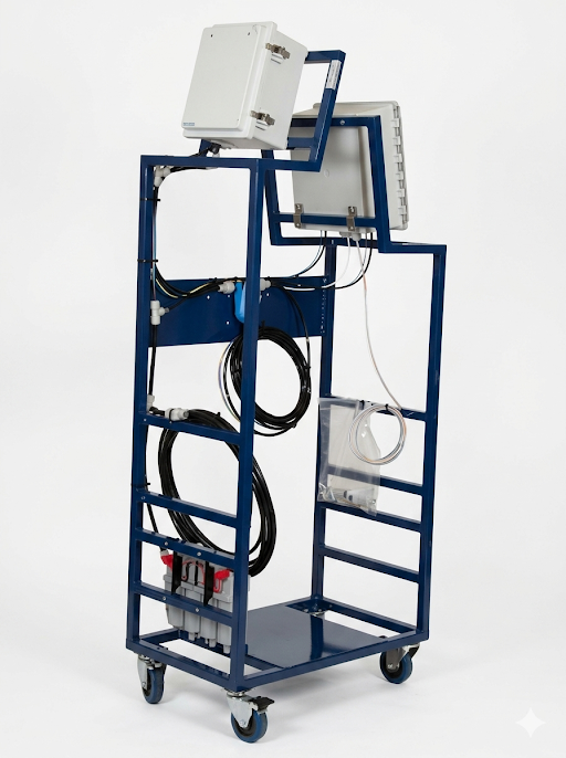
What determines an MS100 grid
A custom grid is selected from the facility layout and humidity load. A floor-area number alone cannot determine the number of delivery points or how to group them into zones.
| Design input | What it determines |
|---|---|
| Room dimensions and obstructions | Grid geometry, mounting, and service access |
| Supply air, exhaust, and open doors | Moisture load and distribution |
| Temperature and target RH by area | Zone boundaries and control strategy |
| Available air, water, and power | Utility sizing and connection locations |
Grid capacity, equipment quantities, and utility requirements are established for the specific project.
From facility drawing to grid layout
Map where humidity matters
Mark the processes, stored materials, and work areas that need humidity control. Identify aisles, cranes, racking, high ceilings, and obstructions that limit mounting positions.
Separate unlike loads
A loading door, oven exhaust, or outdoor-air supply can create a local drying load. Review those areas separately before deciding which delivery points can share a sensor and control zone.
Coordinate installation
Engineering can review mounting, the routing of supply tubing, and access to sensors and controls. Share planned expansion areas so future phases can be considered in the layout.
MS100 application questions
When is a custom grid preferable to individual ES100 units?
Consider an MS100 when the geometry, required distribution, or number of control zones calls for a coordinated grid. For an individual room that can be served from a few wall locations, start with the ES100.
Is there a standard coverage area?
Coverage depends on ceiling height, ventilation, temperature, setpoint, and process losses. Two facilities with the same footprint can require different equipment and layouts.
What controls and options can be specified?
A project may include CPLC control, S Series RH sensors, PB valve control, tubing and fittings, ZeroTDS water treatment, and a building-controls interface. The proposal identifies the selected components.
What should the initial drawing show?
A dimensioned floor plan is ideal. Mark the ceiling height, process equipment, doors, air outlets and exhausts, and preferred utility locations. A rough sketch is enough to start the conversation.
Start your custom grid layout
Send a dimensioned plan or describe the space in the inquiry. Include ceiling height, target RH and temperature by zone, major exhausts or doors, and any mounting or access restrictions.